Blog

Project Bindicator: Final Assembly

Welcome back to my ongoing blog series about my bindicator build!

It’s been a few months since my last proper post about it, I’ve been to Spain and back in that time, done some other things in my life, and my bindicator has been set up and working well for at least the past month!

When last I wrote the parts had arrived and I’d begun modifying the STL files to fit them. That work is now complete and I’ve published it over on printables.com along with the source files in case you wanted to modify them further for your own application.

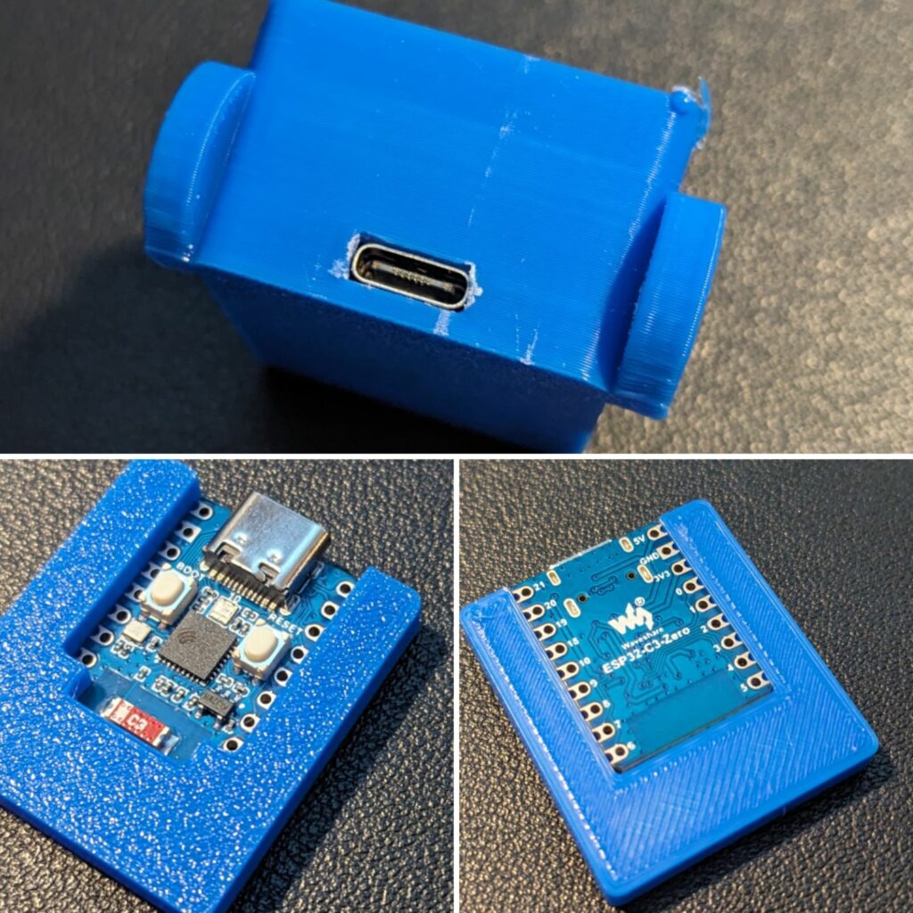
Starting with the original design by CopperLion, I designed a bracket to hold the microcontroller I’d chosen (an ESP32-C3 Zero), slightly enlarged the hole for the USB port to make it suitable for the USB-C plug that the ESP32 uses, and removed two of the three fins from the light baffle so that it would fit an offcut of addressable LED light strip that I had lying around.

From there I printed everything in white (waiting for my order of white filament was actually the biggest delay in the whole process, because Amazon lost it and I had to get a refund and order it again) and it was on to assembly!
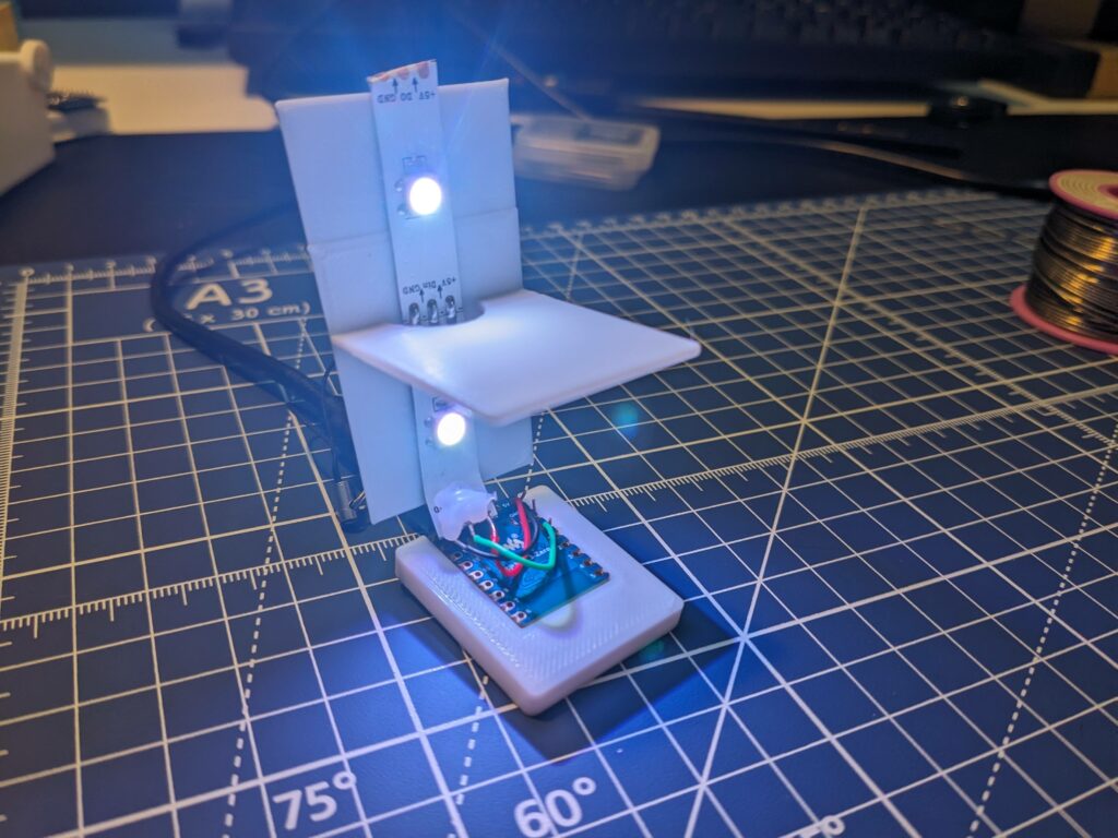
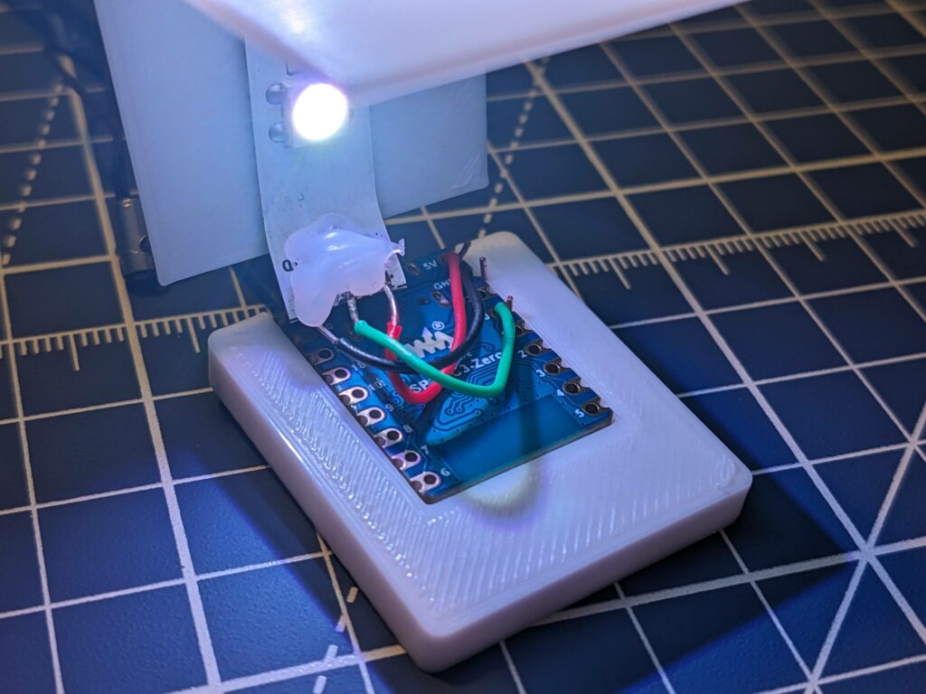
First I soldered three wires from the microcontroller to the light strip – one to the 5v pin, one to ground, and one to GPIO pin for data. Next I peeled the backing off the light strip to reveal its adhesive and stuck it to the baffle, then I glued the microcontroller into its bracket with a little dab of superglue.

With the benefit of hindsight, starting by attaching the baffle was a mistake. The next step was to glue the microcontroller into the bottom of the wheelie bin, and this would have been much easier without the baffle attached. Nevertheless, I managed to get it done.
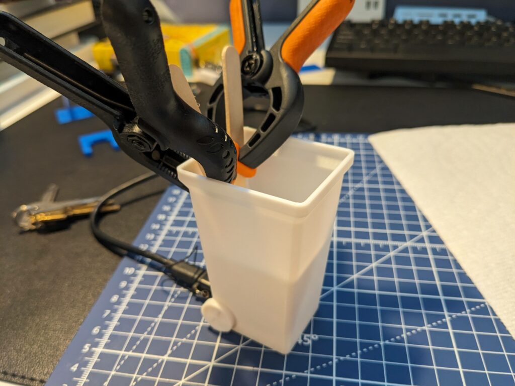
The baffle more or less sits in the right spot without any adhesion but I did put a little dab of glue on the back of it to hold it still, and then finally I glued on the lid. The lid is my least favourite part of the design because it simply rests on top of the bin. Once you’ve glued it in place it’s fine, but gluing it is not the easiest because there’s nothing to hold in place until the glue has set. If I were doing this over I’d like to add a little lip so that it could be inserted and friction-fitted into the top of the bin. On the other hand, that lip would make the top harder to print, so maybe it’s better how it is now? I’m not sure.

With everything working it was on to software, but that’s for a future post. Watch this space!
Shrapnel

…and another update – I’ve made the u-shaped bracket for the microcontroller that I talked about in my post yesterday.

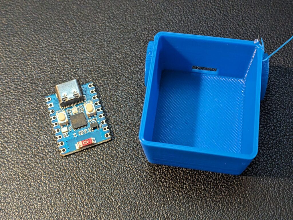
I originally thought I’d need to adjust the hole in the garbage can model to move it upward, but actually the key was putting the microcontroller into the bin with the port facing down.

It does need to be very slightly wider than it currently is, but on my test piece I did that a file and it’s looking good!

Shrapnel

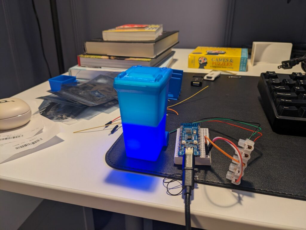
Prototype is alive!

I was worried that only having two LEDs instead of four would result in it not being bright enough, but I’m running it at half brightness with my example code and it seems great.

Next steps are to find a way to fit the tiny microcontroller I’m going to use into the bottom so the USB port lines up for power, and of course print the bin in white.

Blog

Project Bindicator, Part 2: The Parts Arrive

A few weeks after my initial post about my Bindicator project, the microcontroller has arrived in the mail from China and it’s time to get assembling.

Although I’m sticking fairly closely to the original design, there will be a couple of differences that inevitably are going to require modification.

Firstly, the microcontroller itself. The original uses a Wemos D1 Mini which, as I understand it, the garbage can 3D model is designed around and it fits perfectly into the bottom of the bin. I’m using an ESP32-C3 Zero which is quite a bit smaller.

My plan here is to simply print a U-shaped support for the ESP32 that holds it in place, although I also already know that I’m going to need to to raise the cutout for the USB plug very slightly in order for it to align properly. It’s close already, and happily the hole is already an appropriate size for the USB-C connect my ESP32 uses despite having been designed for micro USB. I’m thinking that shouldn’t be too difficult to achieve, though.

The second change I hope to make is to the light source, although I’m not yet sure if my plan for that is flawed. The original design uses four individual RGB LED pixels. I’d prefer to use an offcut of an LED strip I already have lying around, but the problem is that the LEDs are much too far apart.

That said, the original design also divides the bin into four quadrants for the UK’s many different types of garbage, but where I live in Calgary there are only three garbage categories (general, recycling and organic waste) and at most two of those are collected on the same day. I’m therefore going to modify the light baffle from the original design and remove two of the three fins, splitting the bin into two chambers instead of the original four.

I’ve already done this part and made a quick modification to the original STL in Tinkercad, available here.

It remains to be seen if halving the number of LEDs will give me the level of brightness I want, but now that I have a modified baffle printed that’s the next part of the adventure, as I assemble a prototype. If it’s bright enough for my blue test print then it’ll definitely be bright enough for the finished product that I’ll be printing in white.

Watch this space for more to come!

Blog

Making My Own Bindicator

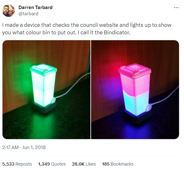
Somewhere around five years ago I saw a semi-viral tweet, and was immediately inspired.

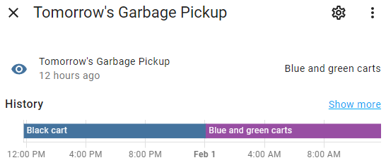
In some ways I’ve been thinking about the ever since. I’ve always loved electronics projects but I didn’t have the capabilities to make a bindicator of my own back then, so I started with the software: the City of Calgary makes their garbage schedule available in iCal format through an API and I’d been subscribed to it via Google Calendar for some time. It wasn’t a difficult task to write a little bit of code to create a sensor in @[email protected] that tells me which carts need to go out that day, and from there it’s even more trivial to craft an automation that sends us each a notification at 7pm the evening before the garbage needs to go out.

This is nice and all, but the idea of a bindacator of my own never really went away, and now that I can do my own , now’s the time!

There are plenty of articles online about how to make this and the original creator has two-part YouTube series that walks us all through it, so I think it might be the perfect first project for combining my new 3D printing capabilities with my aforementioned affinity for little electronics projects.

I don’t 100% know where to start because the microcontroller that I’ve ordered isn’t the exact same one used in the original build, and rather than four individual LEDs my plan is to simply use four LEDs from the end of a spare light strip I have lying around and I’m not certain whether these will fit nicely into the existing 3D model or whether it’ll need some modification to make everything fit (and if it needs modifying – I don’t know yet how to do that).

So in the absence of a solid plan I’ve opted to get started by getting started. As I write this the 3D model is printing in the other room and @[email protected] tells me it has an hour to go. I don’t know that this will be a quick project because I expect to learn a lot as I go, but I will keep you all up to date on how I get on!